If you somehow got here with going from the start, you can head back to Page 1 of this guide. Otherwise, read on.
Attaching the Region Mod PCB
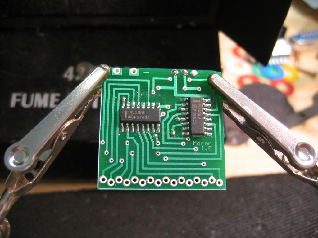
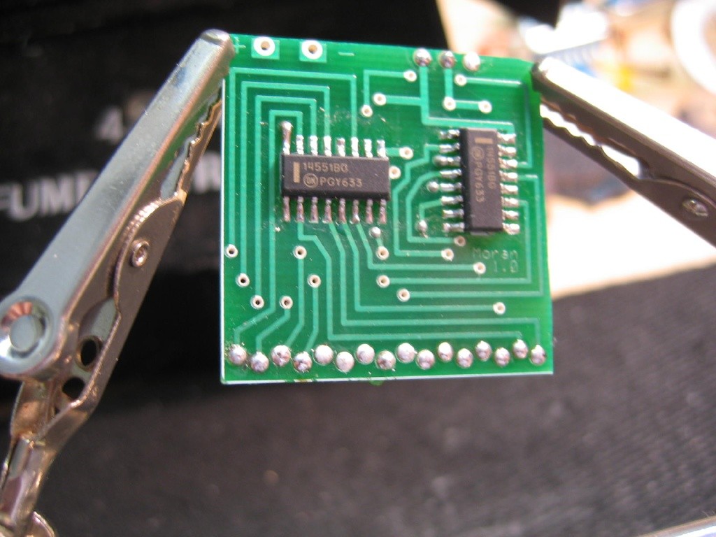
At this point you should have 16 wires dangling from you currently helpless cart slot of your PC Engine/CoreGrafx/CoreGrafx II. Ideally you have them color coded for PCB side and HuCard slot side. Now take the little PCB you received from me and hold as shown in the photos below. I use some "helping hands" which are available many places including Radio Shack. They really come in very handy for many different projects. Now looking at the PCB you'll see lots of holes at the edges. To make the soldering easier later and free up a hand, I like to prefill these holes with solder before adding the wires. To do so, heat up the edge of the hole and touch the solder to the hole. It should form a positive meniscus, like a bubble. DON'T USE TOO MUCH SOLDER. If you flip the PCB over and it's pouring everywhere or the different holes are now connected by a river of solder, you've added way too much. Get out that soldering braid and clean up your mess! Providing you did a good job is should look like the second photo. Fill the holes on the bottom and the top right 3 holes.
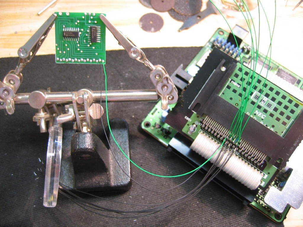
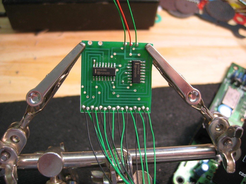
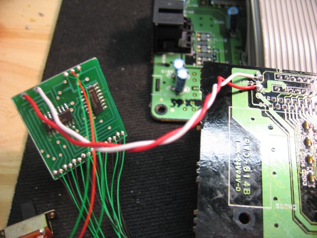
Time to get the PCB acquainted with the PC Engine now. We're going to wire it such that the #15 pin from the PC Engine/CoreGrafx ends up attached to the far left of the PCB. You can wire in either direction, but I usually go from pin #23 across to #15. So first split the wires so the slot wires (the green ones below) go up and away from the PCB wires (black below). Just keeps them obvious. Now, we are going to attach the wires alternating PCB and Slot wires as shown. Specifically, the wires go as such:
| PCB15 | Hu15 | P16 | H16 | P17 | H17 | P19 | H19 | P20 | H20 | P21 | H21 | P22 | H22 | P23 | H23 |
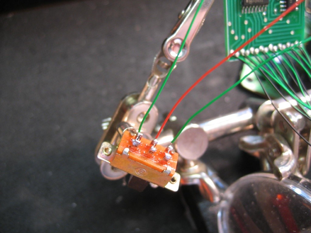
To connect the wires, heat up the hole and then insert the wire end. Hold in place until the solder cools, about 2 seconds. Should make a tight connection. Lastly, attach three 5" pieces of wrapping wire to the three holes in the upper right of the board, shown as green/red/green in the second picture. These wire will connect to your SPDT or DPDT switch with the red wire being the middle wire of the switch.
Adding a switch to the PCB
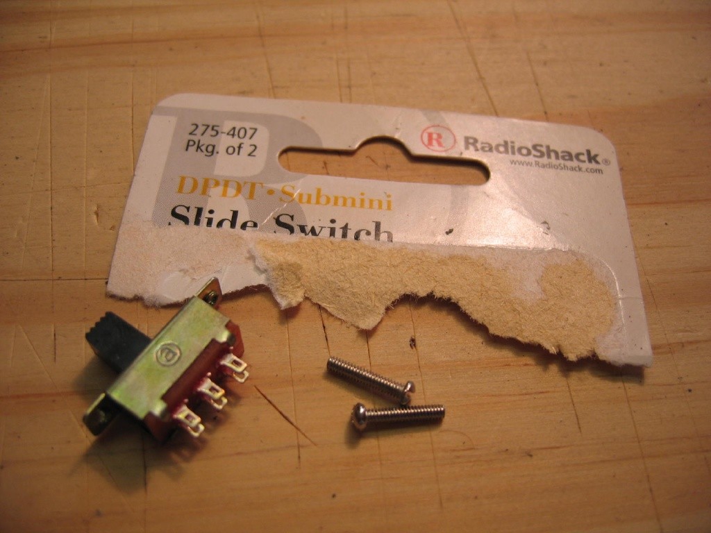
For the mod, what you are doing here is switching between US and Japanese regions by effectively flipping the 8 pins you cut and soldered to. The PCB you just connected does this electronically using two 4PDT chips. For this to work, you need a switch to toggle between the two states and power to run the chips. The 3 wires you attached are going to a switch, specifically an SPDT. That stands for "Single Pole Double Throw", meaning one connection in that flips between two connections out. In the pictures below, I show a DPDT switch which just adds a second sets of connections in case you wanted to flip two switches at once. It's used here because that's the one I happened to have on hand. This exact one comes from Radio Shack in a package of 2 and is nice because it has threaded holes and screws on it (PLEASE NOTE: I'm not sure the cardboard shown below is the exact match to the switch shown. The switch is roughly 3/4" long, so go with that). Thread the wires through the eyelets on the switch and solder them down. If using the DPDT, thread the wire through both sets of loops and solder both.
Powering the Region PCB
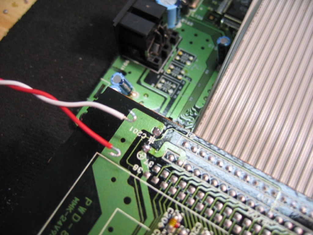
Now we're going to connect the PCB to power as I noted above. Conveniently you can pull the +5V and Ground right off of the back of the HuCard slot. And even more conveniently, the +5V is marked as (+) and ground is the big ol'patch band on the side. In the pictures here, I use 5" of twisted pair wire where the red is for +5V and the white is ground. Tin the tips of the wire first and also add some solder to the points you want to solder to. Then solder them together. Tin the other end of the wire and thread through the + and - holes on the region PCB. Solder the wires to the board now. You're fully connected!
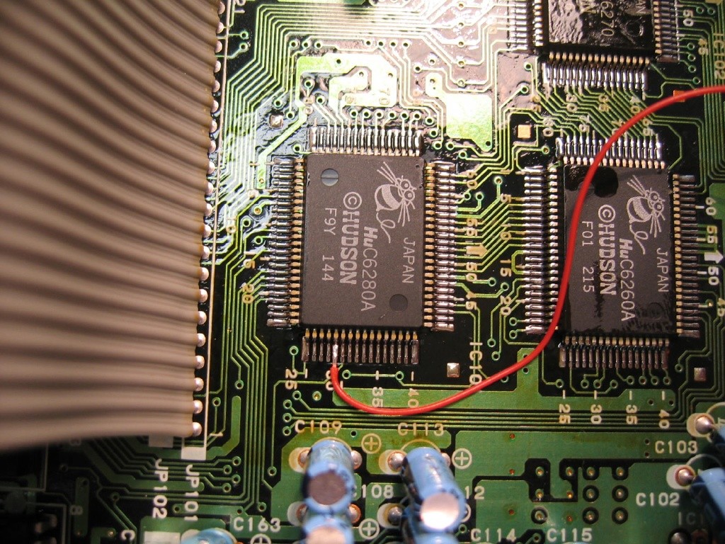
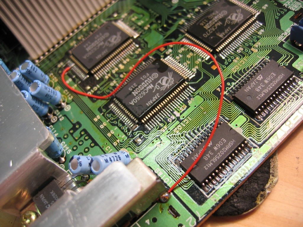
Grounding Pin #29, a.k.a. Defeating Region Lockout
| Now here's where you may hae to sweat a bit. Not only do US and Japanese systems have 8 switched pins in the HuCard slot but there is some manner of region check run by the processor. This is readily defeated by simply grounding pin #29 of the Hu6280 processor. As it turns out only the Japanese systems run this region check so you only have to do this grounding on the Japanese systems. The systems are outlined to the right here, but all you need to remember is if it's a Japanese system you have to ground pin #29. |
|
|||||||||||||||||||||
To do this, you'll need to attach a wire to pin #29 and then the other end to ground. First, touch some solder to the tip of your soldering iron and then to the pin. This is IMPORTANT: make sure you don't short the neighboring pins! Just look to make sure there is no stray solder or it could cause problems. If there is, simply use that soldering braid again, just do so lightly. Remember that you don't need to over do it with the soldering, just enough is all. Take a piece of wire, stripped to about 1/16" on both ends and tin both ends of the wire. It won't look like much is there, but it's enough. Carefully place the wire on top of pin #29 and then heat them together with the soldering iron. Using the narrow tip soldering iron will make this easier for you as well. When done, you can check your work by using a multimeter set to conductivity and check that the pins aren't shorted by solder. Once you're confident you have a good and precise connection to the #29 pin, solder the other end of the wire to a ground point, any. I use the one near the switch. Now for some pics. When done, you can secure the line with a piece of electrical tape or a spot of hot glue. Just don't glue over the pins in case you have to do the soldering again :)
We're in the home stretch! Go on to Page 3 to read about cutting that hole in the case and mounting your switch.